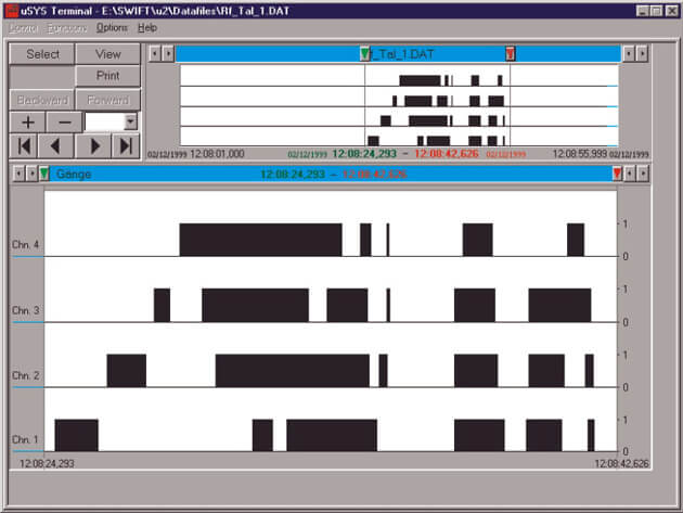
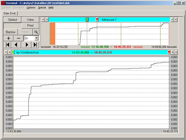
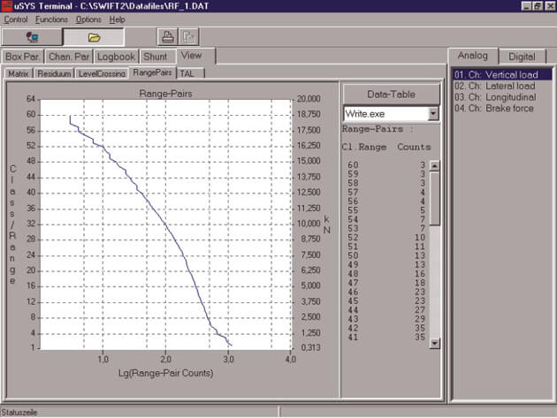
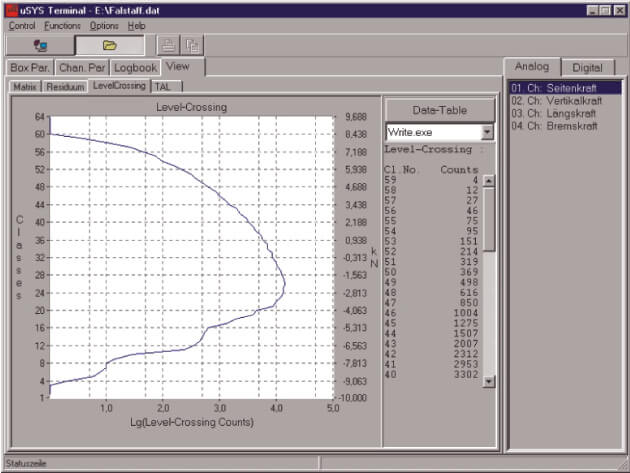
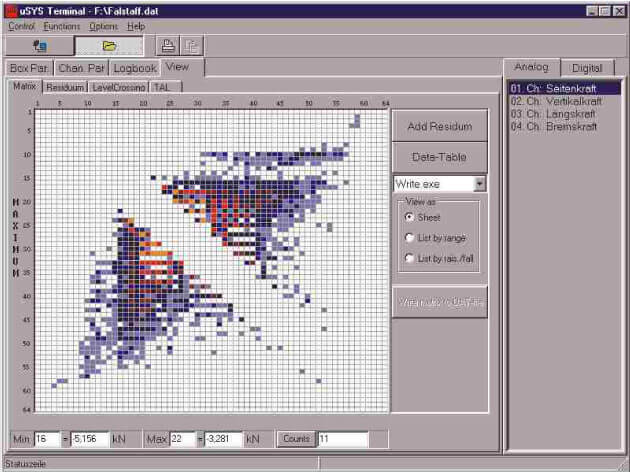
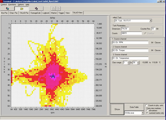
|
Rainflow - RF
With the method Rainflow closed hysteresis loops are recognised and stored in a resulting matrix. Not closed hysteresis are stored as residue. The programmable amplitude suppression assures that small signal variations are filtered out.
|
|
|
| |
 |
|
|
Level Crossing - LC
The result of the method Level Crossings is derived offline from Rainflow. The crossing of levels is counted.
|
|
|
| |
 |
|
|
Range Pairs - RP
The result of the method Range Pairs is derived offline from Rainflow. Range Pairs are counted as cumulative frequency distributions.
|
|
|
| |
 |
|
|
Transient Mode with Trigger - TM
With the method Transient Mode with trigger the samples are taken in time intervals which can be defined channel per channel by the user (up to 2.000 Hz per channel). Also in this method the trigger function is a help for reducing the amount of data stored.
|
|
|
| |
 |
|
|
Time at Level - TaL
This one-parametric evaluation method gives the time that a signal is at a certain level. When the measuring signal passes through a certain class during measuring several times the time in this class is added up.
|
|
|
| |
 |
|
|
Time at Level multidimensional - TaLnD
The time at level multi-dimensional (TaLnD) determines the duration of time for which two or three different signals stay at a certain level. The result is stored in a two or three dimensional matrix.
|
|
|
| |
 |
|
|
Sequential Peaks with Time and Master/Slave Concept
With the method Sequential Peaks and Troughs with time and master/slave algorithm the turning points of defined master channels are taken with time as in the SQTM method. Additionally the instantaneous values of slave channels which are assigned to this master channel are taken. Any channel of the Box can be defined as a master channel and any other channel of the box can be defined as a slave to this master so that e. g. in a 20 channel box as a maximum 20 master channels can be defined and altogether 132 slave channels.
|
|
|
| |
 |
|
|
Digital Time - DT
The method “Digital Time” evaluates digital signals.
With this evaluation method the digital input channels are sampled and every change in the status of the channel is registered with time. The result of this evaluation method is presented in a logic diagram and in a table. This method is used for example to know when a clutch is engaged or disengaged, when a switch is in the on or off position, when a certain gear is shifted in the gear box or for example when the starter is activated.
|
|
|
| |
 |
|
|
Damage Evolution - DE
The Damage Evaluation method is based on the Rainflow counting and the damage calculation according to Palmgren-Miner. Based on the user defined Wöhler-line the recorder constantly calculates the actual relative damage sum from the Rainflow matrix. The sum of damage is stored on a regular basis together with a time stamp. The demand interval can be set between 0.1 seconds or several minutes. As a result of the measurement, a curve will be generated showing the progress of the relative damage according to time. A sharp increase in the graph is equal to high damage of the vehicle. Via the time stamp these events can be correlated.
|
|
 |
| |
 |
|
|
DAM - Damage
This method allows a damage calculation based on Rainflow matrices.
|
 |
|
| |
 |
|
|
Loop Control
This new analysis method is an external trigger for Damage Evolution.
|
 |
|
| |
 |
|
|
RFX – Rainflow with variable number of classes
The Rainflow Extension RFX allows the selection of the number of classes used for the RF-classification. It supports 64x64, 128x128 and even 256x256 classes. As the required memory space increases dramatically with the number of classes this parameter can be defined for each channel individually. Thus enabling best possible memory usage.
|
 |
|
| |
 |
|
|
DTCR – Direct to Card Recording
Like the method TM, DTCR is meant for the recording of signal time histories. Although, the data is not stored internally but is written directly to an inserted PCMCIA-Flash card. Cards with a size of more than 16GB are available and thus allow long term recording of signal time histories at high sampling rates with up to 2Gbyte length.
The sampling rate can be set by the user individually for each channel to a maximum rate of 2kHz per channel. The start and stop of the measurement is controlled by an external digital signal or by switching the recorder’s power supply directly.
|
 |
|
| |
 |
|
Virtual Channel – Formel „Low Pass“
This formula implements a first order digital low pass filter. The cut-off frequency of the filter and the source channel can be selected by the user. The cut-off frequency may range from 1/40 to 1/400 000 of the system sample rate. For the standard sample rate of 2kHz this results in a range of 0.005Hz to 50Hz. Because of the availability of low and very low frequencies this formula is best suited to measure the quasi static part of any dynamic value.
|
 |
|
| |
 |
|
|
Extensions for the GPS-Recording Software
GPS-Slave-Channels, slave channels for GPS-Datastream
With the standard GPS-Option only the time and geographic position is stored in the GPS-Data Stream. With the Slave-Channel-Option the recorded data stream is extended by the data of one or more (up to four) freely selectable analogue channels. Typically this option is used to store route related information like engine temperature, attitude or track speed. As the set of selected slave channels is only stored once per way point the memory consumption – 2 Bytes per Channel (and way point) – is quite low.
|
 |
|
| |
 |
|
|
Software-Option
Automatic Data Transfer
The ADT software is a stand-alone software package that permits the data transfer from MATCH or MICRO recorders to a client PC. The programme is started from the command line, and all special functions (e.g. Start, Stop, Delete, etc.) are controlled through the command line parameter. This software allows the Stop, Read-Out, Delete and Re-Start of a recorder to be completely automatic. Through the use of the standard Windows service “Scheduled Tasks”, the regular Read-Out of one or more recorder can be performed. Together with the Remote Link (RL) option, this can naturally be extended to remote systems.
|
|
|
| |
 |
|
|
Software-Option
Virtual Analog Channels
Optional virtual channels perform certain mathematical calculations between signals from digital or analogue real channels. The virtual channel has the full functionality of an actual channel but are not directly connected with an actual sensor.
|
| |
 |
|
|
Software-Option
Virtual Power Off Value für RF (VOPV-RF)
If the power of the data acquisition system is turned off before all measuring systems reach the zero power value, those data are lost and cannot be included in the evaluation matrix, e.g. the motor speed = zero if the motor idles after the power is turned off. The VPOV function allows the setting of a virtual power-off value which will be included in the data record and which corresponds to the known power-off value of the system.
The value can be set for each individual channel and the function can be activated or deactivated for each channel.
|
| |
 |
|
|
Software-Option for Evaluation Methods
Highspeed für RF + TaL
If not all of the 20 possible analogue channels of the MICRO-II recorder are in use, the sample rate in RF and TaL mode can be increased remarkably. The maximum sample rate for each channel can be determined by dividing 40 kHz by the number of channels used. More details are available on request. |
| |
 |
|
|
Software-Option for Evaluation Methods
Data Sets - DS
The additional function “Data Sets” to the methods RF, TaL and RF+TaL allows the online classification of the total set of results into separate data sets. During the measurement, the differences between the various measurement parameters can be evaluated. For example, a car first travels along a country road (first data set), then on a gravel road (second data set), followed by a motorway (third data set) before finally driving in town (fourth data set). |
| |
 |
|
|
Software-Option
N-ADJUST-ALL
The n-adjust-all function allows the simultaneous adjusting of several or all analogue channels. The function is helpful when offsets from several channels need to be repeatedly adjusted within short time periods, simplifying the procedure of channel adjustment in multi-channel applications. Each channel can be individually set to be included in the n-adjust-all function and also the actual offset value can also be defined for each channel.
|
| |
 |
|
|
Evaluation Method
OLE Offline-Evaluation
1. Offline evaluation of: TM according to RF, LC, RP and TaL.
2. Offline evaluation of: SQTMS according to RF, LC, RP.
|
| |
 |
|
|
Software-Option
Data Export to Diadem
Export RF, LC, RP + TM to Diadem |
| |
 |
|
Additional Hardware/Software Options
- Network-Option
- Remote-Link-Option
- Fast-Data-Transfer
- CAN-Bus Support
- GPS-Option
|
|
|